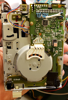
Using a Mitsumi D359M3D, we fully formatted a floppy disk for the first time on the Convergent Technologies AWS Turbo.

How did we do it?
As many times before, we thank Jim Drew for his help, coaching, and friendship. Following Jim's advice, we made the following modifications to the 3.5" floppy drive
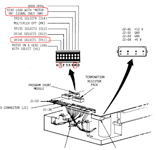
First, we added 1kΩ pull-up resistors on all of the drive input lines that we needed to experiment.
This keeps the signals from "floating", and doing unpredictable things for all tests where we left these lines open.
Next, we created a modified cable adapter, and after countless experiments, we ended up connecting the floppy to the AWS like this:
So, if you watched the video, you noticed the timing difference that the machine hardware uses when writing to tracks 43 and higher...what a concept! TWO different timings on the same disk!
What other systems did this?
You can download the flux capture files I show in this video from here, and analyze them yourself!
BTW, from looking at the resulting .scp floppy image capture, Jim says "Whatever drive that is - you probably should throw that away unless you are powering it with something really crappy because the drive speed is all over the place while rotating."
We shall see about upgrading soon, Jim...soon!!!
For context, the original floppy drive is a
Control Data / Magnetic Peripherals BR8B2-A 9409T
P12-02 = ?
P12-04 = P9-16 SIDED-
P12-06 = ?
P12-08 = P9-11 INDEX-
P12-10 = P9-19 DS0-
P12-12 = ?
P12-14 = ?
P12-16 = P9-22 HL0+
P12-18 = P9-07 DIRECT-
P12-20 = P9-09 STEP-
P12-22 = P9-21 WRDATA-
P12-24 = P9-72 WRGATE-
P12-26 = P9-70 TRACK0-
P12-28 = P9-18 WRPROT-
P12-30 = P9-24 RDDATA-
P12-32 = P9-16 2SIDED-
P12-34 = P9-10 READY-
The "Factory Equipment" Floppy Drive Lines
At rest:
In Action:
[image missing, sorry]
agentb — Today at 2:46 PM
pin 4 - ok, so this one is a bit odd. it's labeled "In Use" and a signal GOING to the 9409T drive but in actuality it is a signal COMING from the drive as far as I can tell. At least if you look at the FDC (8272) schematics. in the FDC schematics, there are two lines (P9-6 SIDED-, and P9-18 WPROT-) that run into a single pin on the 8272. This is the WP/TS pin 34 on the 8272. When the 8272 is in r/w mode, it looks at the WPROT- signal to make sure the disk isn't write protected. When in "Seek mode", it looks at the SIDED- signal to see if it's a double sided disk. (not to be confused with P9-16 2SIDED- which is just the side select) There's an error in the manual stating SIDED- is J9-16, it's actually P9-6 as you can see in the schematic. There's a chance the 9409T doesn't actually provide the SIDED- signal and in fact is receiving something for IN USE.
anyway, this is a bit beside the point because we AREN'T using the FDC board with the 8272, rather we are using the HDC with the Signetics. SOOOOOO, you will not be able to find references to the SIDED- line in the HDC schematics. So my thought is the SIDED- line isn't relevant for the HDC board.
pin 6 - drive select 4, shouldn't be used so looks to be grounded
pin 8 - INDEX-, so active low, looks to be high which makes sense
agentb — Today at 2:51 PM
pin 10 - Drive Select 1, aka DS0- looks to be blipped active low periodically. and then you see the READY- line (pin 34) go active low once the drive is selected which seems to make sense. Drive READY- should only be active (low) when the drive is selected
pin 12 - drive select 2, same as drive select 4, shouldn't be used
pin 14 - drive select 3, aka DS1- used for the hard drive (and alternatively also Floppy 1, the 2nd floppy)
Also being blipped active low, I think there's a part in the signetics code where it keeps looking for a change of status in the READY- line -- this might be what's going on with these blips
pin 16 - Motor ON (active low) aka head load 0 (HL0-) looks to be active low which seems to make sense
pin 34 - READY- (aka DOOR OPEN+), looks to be going active low as a response to having been drive selected on pin 10 (DS0-)
that's my thoughts on the readings
my thoughts on the wiring
--------------------------------------------------------------------
2022-02-12 UPDATE:
Jim Drew has helped me design a simple circuit to make Pin 34 follow Pin 10/Pin 14. (Just connecting Pin 10 or Pin 14 to Pin 34 just didn't make it work...


No comments:
Post a Comment